 |
3D Germanium MESFET |
 |
A simple 3D MESFET has been simulated by means of Aeneas in order to test its capabilities and reliability. The MESFET has a simple n+-n-n+ structure with a channel lenght equal to 0.25 micron. The MESFET has two n+ regions of 0.25 micron, which means that the diode is 0.75 micron in total. The doping regions are n+=1.e23/m^3 and n=1.e21/m^3. The applied voltages are equal to 0.8 Volts and -0.4 for the bias and gate respectively.
The devices is defined by means of an input file which describes the doping regions, the boundary conditions, the applied voltage, the number of simulated particles and so on. Furthermore, a mesh file describes the diode shape. The input ASCII file is reported at the end of this page, while various 3D pictures obtained using Aeneas are shown in the following.
Please, note that the Monte Carlo simulation is coupled consistently to an unstructured mesh, which is a great advantage for novel 3D semiconductor devices.
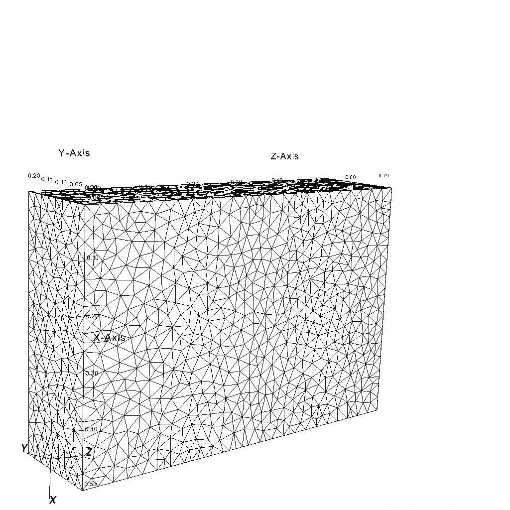
The mesh is introduced by means of an ASCII file described the dimensions and geometry. Here is a graphical representation.
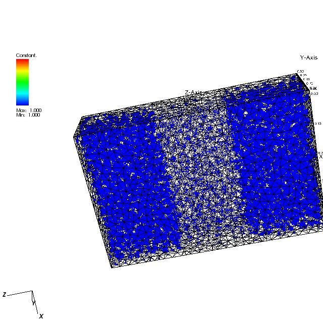
In the following we show the particles initial position in the simulated diode.
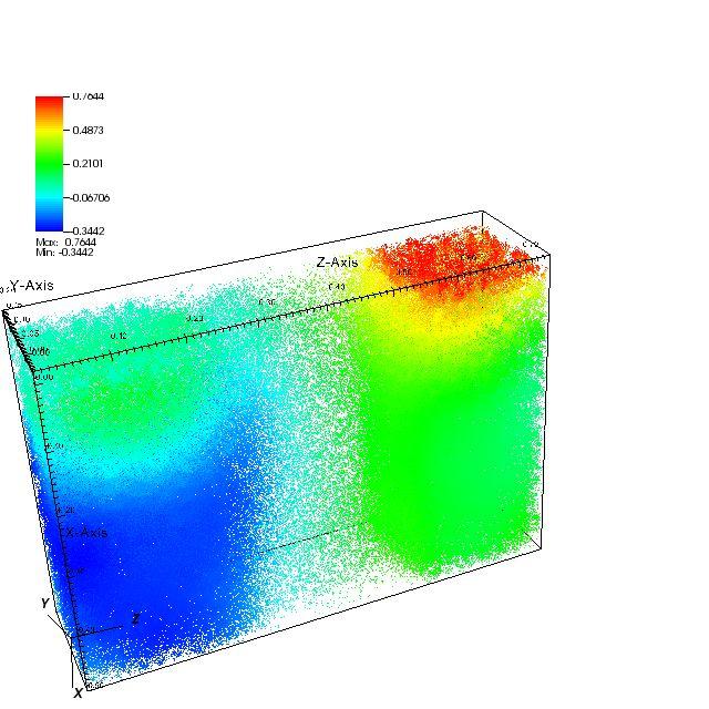
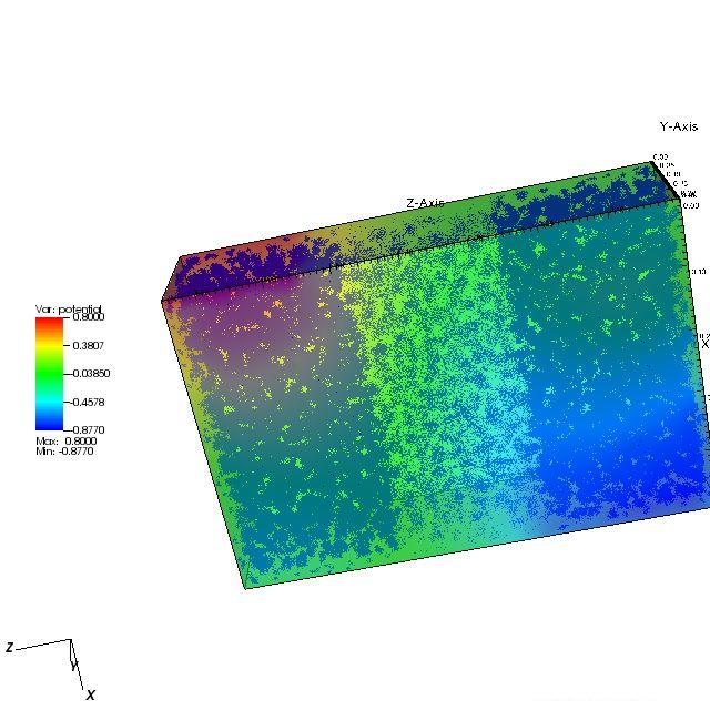
In the following picture, the final computed electrostatic potential is shown in function of the final particles position, i.e. every particle has a color coupled to the potential it is feeling.
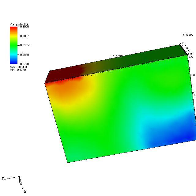
The final calculated potential field is reported in the following picture.
Finally, we report the particles in a trasparent potential.
The input file for this diode simulation reads :
# input file for the simulation of a Germanium
MESFET
# dimensions : 0.5x0.2x0.75 microns
# bias : 0.8 Volts
# gate : -0.4 Volts
# mesh file : device.mesh
#
www.southnovel.eu
# time step in seconds
TIMESTEP
0.015e-12
# final time of simulation in seconds
FINALTIME
6.000e-12
# the code starts the mean average for velocity
# and energy at the last MEDIA time steps
MEDIA 500
# lattice temperature in Kelvin
LATTICETEMPERATURE
77
# save the data every number of steps
SAVEEVERYNUMSTEPS
8
# impurity density in 1/m^3
CIMP 1.e14
# contact type and applied voltage (meters, volts)
CONTACT X 0.0
0.5e-6 Y 0.0
0.2e-6 Z
0.75e-6 0.75e-6 INSULATOR
CONTACT X 0.0 0.5e-6
Y 0.0 0.2e-6
Z 0.0 0.0
INSULATOR
CONTACT X 0.0 0.5e-6
Y 0.0 0.0
Z 0.0 0.75e-6
INSULATOR
CONTACT X 0.0 0.5e-6
Y 0.2e-6 0.2e-6
Z 0.0 0.75e-6
INSULATOR
CONTACT X 0.5e-6
0.5e-6 Y 0.0
0.2e-6 Z 0.0
0.75e-6 INSULATOR
CONTACT X 0.0 0.0
Y 0.0 0.2e-6
Z 0.0 0.75e-6
INSULATOR
CONTACT X 0.0 0.0
Y 0.0 0.2e-6
Z 0.0 0.2e-6
OHMIC 0.0
CONTACT X 0.0 0.0
Y 0.0 0.2e-6
Z 0.55e-6 0.75e-6
OHMIC 0.8
CONTACT X 0.0 0.0
Y 0.0 0.2e-6
Z 0.25e-6 0.50e-6
SCHOTTKY -0.4
# statistical weight, i.e. the number of particles
in cell
# which have the maximum density value
STATISTICALWEIGHT
50
# the Poisson solver can be 1, 2, 3 or 4.
# it is used to select the method for solving the Poisson equation
POISSONSOLVER
4
# the tollerance for the Poisson solver
POISSONTOLLERANCE
1.e-16
# maximum number of iterations for the Poisson
solver
POISSONITMAX
1500
# material specification (Si is the default)
MATERIAL X 0.0
0.5e-6 Y 0.0
0.2e-6 Z 0.0
0.75e-6 GERMANIUM
# donor density of the device in 1./m^3
DONORDENSITY X
0.0 0.5e-6 Y
0.0 0.2e-6 Z
0.25e-6 0.5e-6 1.e21
DONORDENSITY X 0.0
0.5e-6 Y 0.0
0.2e-6 Z 0.0
0.25e-6 1.e23
DONORDENSITY X 0.0
0.5e-6 Y 0.0
0.2e-6 Z
0.5e-6 0.75e-6 1.e23
# quantum effective potential taken into account
QUANTUMEFFECTS
# end of input file
